Introduction
Overview
When industrial devices are connected to an external amplifier, you can control whether audio is output to the amplifier based on the application scenario.
During normal calls, the amplifier should be OFF and only the built‑in speaker used. During broadcast or emergency announcements, the amplifier must be activated.
This document describes two control methods for different device models.
Applicable Models
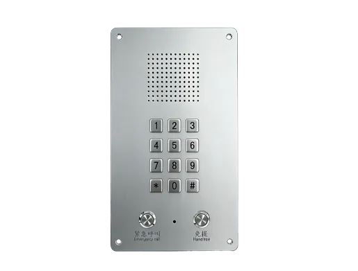
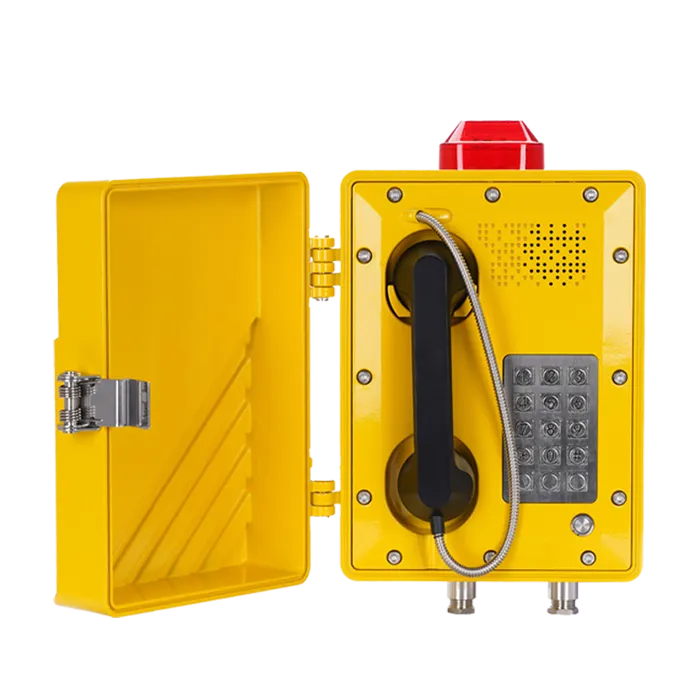
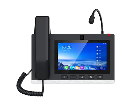
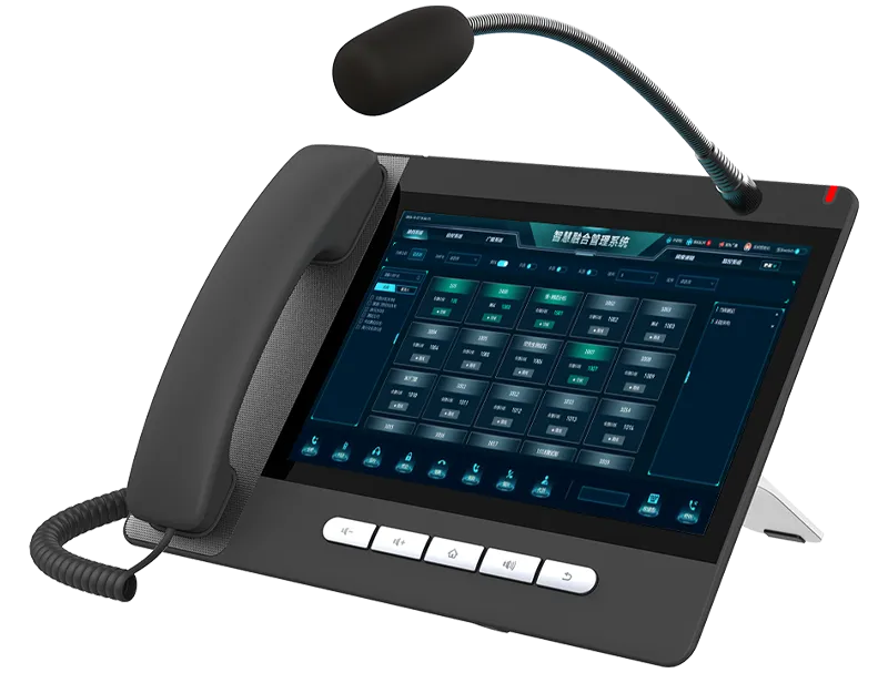
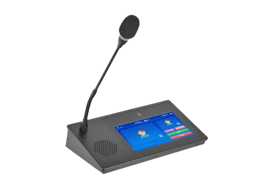
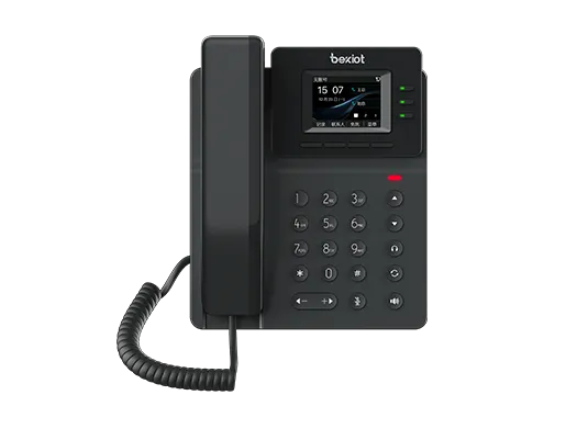
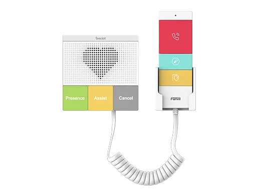
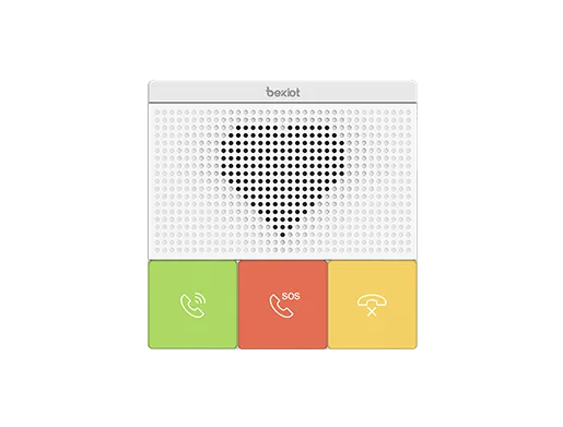
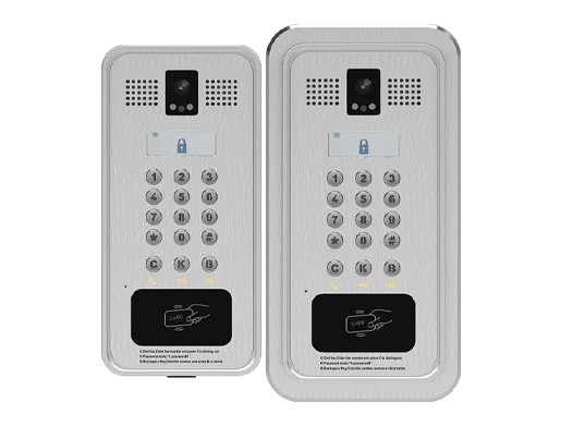
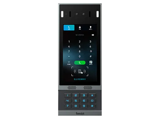
BHP‑SOS10, BHP‑SOS10V, BHP‑SOS10D, BHP‑SOS11V, BHP‑SOS11V2, BHP‑SOS16, BHP‑SOS16V, BK‑ROIP‑PA2, BK‑ROIP‑PA2S, BK‑ROIP‑PA3, BHP‑SOS12.
Prerequisite Preparation Tools
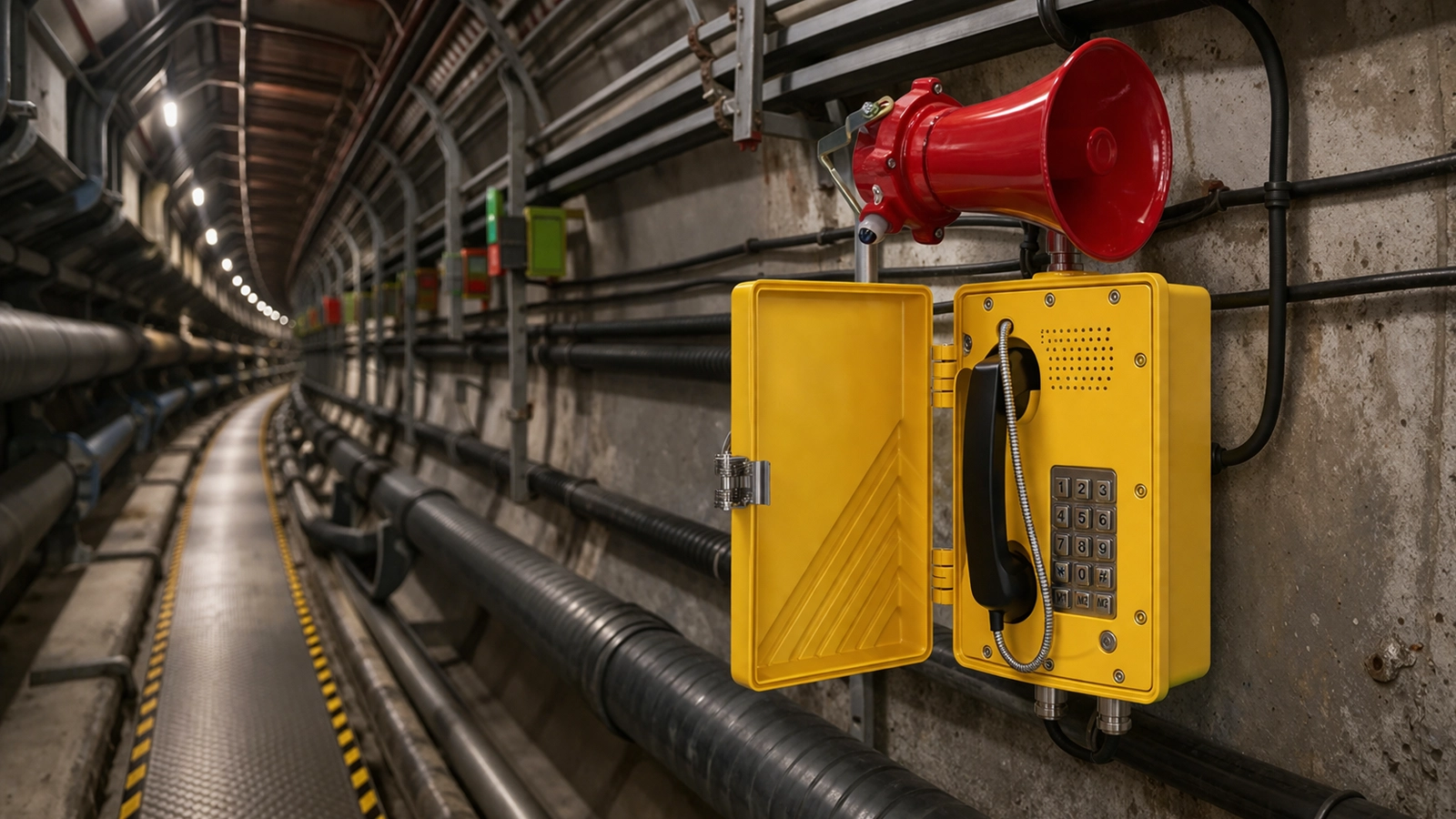
① One supported device (BHP‑SOS16V as example), PoE switch (or DC power supply), one amplifier, one speaker. Connect the amplifier to the device and the speaker to the amplifier. Connect the device to the switch.
② One debugging computer connected to the same switch to ensure network connectivity.
Device and Computer Connection Diagram
Connect the BHP‑SOS16V and computer to the same switch. The connection diagram is shown in Figure 1.

Figure 1 Device and Computer Connection Diagram
Control Amplifier Audio Output
Amplifier output can be controlled either by enabling the Audio Out interface or by using a relay to switch the amplifier power. Both methods are explained below.
Control via Audio Out Interface
This method applies to: BHP‑SOS10 series, BHP‑SOS11 series, BHP‑SOS16 series, BK‑ROIP‑PA2, PA2S, PA3.
Note: BK‑ROIP‑PA2/PA2S use the Headset interface; PA3 uses Line Out. i10/i11 series require custom 2‑pin MX1.25 wiring.
Configure via the Web UI:
(1) Log in to the Web UI (default username/password: admin).
(2) Go to Intercom Settings → Media Settings → Media Settings.
- Set Enable External Speaker to Handfree&&Lineout.
- Set Lineout Trigger Status to Intercom Callee.
Parameter descriptions:
- Handfree&&Lineout: Enables both handfree and lineout audio.
- Lineout Trigger Status:
- Ringing: Trigger when ringing
- Caller (Talking): Trigger when making calls
- SIP Callee (Talking): Trigger when receiving SIP calls
- Multicast Callee: Trigger when receiving multicast
- Intercom Callee: Trigger when receiving intercom calls
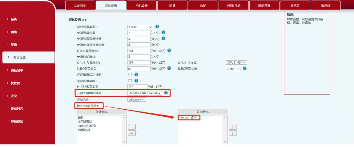
Figure 2 Audio Out Control Diagram
Control via Relay Output
This method applies to all listed models including BHP‑SOS12.
(1) Output Port Specifications
| Model | BHP‑SOS12 | BHP‑SOS16/16V | BHP‑SOS10/11V/PA2 | BK‑ROIP‑PA2S |
| Output Ports | 2 | 2 | 1 | 1 |
| Rating | DC 30V/1A
AC 30V/1A | DC 30V/2A
AC 125V/0.5A | DC 30V/1A
AC 125V/0.5A | DC 30V/1A
AC 125V/0.5A |
(2) Wiring the Amplifier (Dry Contact Example)
① For BHP‑SOS16V external power mode: connect JP1 pins 2–3, leave pins 1 and 4 floating, as shown in Figure 3.
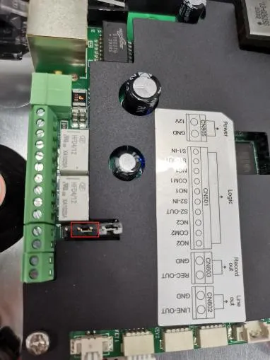
Figure 3 Jumper Connection Diagram
② Wiring:
- Power positive → Amplifier positive
- Power negative → Device COM
- Amplifier negative → Device NC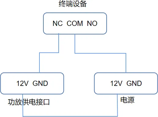
Figure 4 Amplifier Wiring Diagram
③ Audio wiring:
- Amplifier left audio → Device Audio Out +
- Amplifier GND → Device GND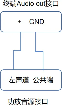
Figure 5 Audio Input Wiring
(3) Output Port Configuration
① Go to Security Settings → Output Port Settings.
② Check Output Port 1 (or 2).
③ Check Trigger by Call State and enable Intercom Callee.
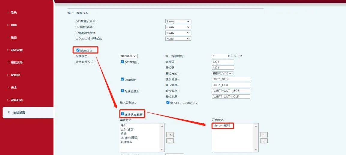
Figure 6 Output Port Configuration
When the device receives an Intercom Callee event, COM and NC close, turning on the amplifier.