LC Resonant Circuits: Principles, Design, Applications, and Stability Analysis
Learn how LC resonant circuits work, how to design series and parallel resonant networks, where they are used in filters and oscillators, and which factors affect frequency stability, Q factor, and real-world performance.
Becke Telcom
LC resonant circuits are among the most important frequency-selective building blocks in electronics. By combining an inductor and a capacitor, engineers can create a network that stores energy, exchanges it between magnetic and electric fields, and responds strongly around a specific frequency. This behavior makes LC circuits essential in radio-frequency systems, analog filters, oscillators, impedance-matching networks, and many sensing and signal-conditioning designs.
Although the basic theory is elegant, practical LC resonant circuits are never completely ideal. Real inductors have winding resistance, real capacitors have dielectric loss, and PCB traces introduce parasitic inductance and capacitance. As a result, resonance in actual hardware is shaped not only by the nominal values of L and C, but also by Q factor, loading, component tolerance, thermal drift, and layout quality. A useful technical article therefore needs to cover both principle and implementation.
LC resonant circuits are foundational elements in frequency control, filtering, and oscillator design.
What Is an LC Resonant Circuit?
An LC resonant circuit is an electrical network built around an inductor (L) and a capacitor (C). These two passive components interact in a distinctive way. The capacitor stores energy in an electric field, while the inductor stores energy in a magnetic field. When connected together, they can transfer energy back and forth, creating a resonant response at a particular frequency.
That special frequency is called the resonant frequency. At resonance, the inductive reactance and capacitive reactance are equal in magnitude and opposite in effect. In theory, the reactive components cancel each other, leaving the network dominated by its resistive behavior. In practice, the exact response depends on whether the circuit is configured in series or parallel, and on how much loss is present in the real system.
In simple terms, resonance occurs when the inductor and capacitor “balance” each other at one frequency more strongly than at any other point in the circuit’s operating range.
The Working Principle of LC Resonance
Energy Exchange Between Electric and Magnetic Fields
The operating principle of an LC resonant circuit starts with energy storage. When a capacitor is charged, it stores energy in an electric field. When current flows through an inductor, the inductor stores energy in a magnetic field. In an ideal lossless LC network, energy moves repeatedly from the capacitor to the inductor and back again.
This periodic exchange produces oscillation. As the capacitor discharges, current rises through the inductor and creates a magnetic field. When the magnetic field collapses, it drives current onward and charges the capacitor with opposite polarity. The result is a repeating cycle whose frequency is determined by the values of L and C.
This is why LC circuits are often called resonant or tank circuits. They do not simply pass current like ordinary passive networks. Instead, they exhibit a natural frequency behavior that can be used to select, reject, or generate signals in a controlled and predictable way.
The Resonant Frequency Formula
The most familiar equation in LC circuit theory is the resonant frequency formula. It shows that the resonant frequency depends on both inductance and capacitance rather than on either element alone. When inductance increases, the resonant frequency decreases. When capacitance increases, the resonant frequency also decreases.
The standard expression is written as follows:
f = 1 / (2π√LC)
This formula is often the starting point for design work. However, engineers should remember that it describes the ideal resonant point. In real circuits, parasitic resistance, stray capacitance, and load interaction can shift the actual measured resonance away from the purely calculated value.
Why Resonance Matters in Electronics
Resonance matters because it gives a circuit frequency selectivity. Instead of reacting equally to all frequencies, an LC network shows a strong preference around a narrow band. This characteristic is especially valuable in communication systems, where signals must be separated, filtered, amplified, or generated at precise frequencies.
In radio receivers, resonance helps isolate one channel from many others. In oscillators, it helps define the oscillation frequency. In filters, it sharpens passband or stopband behavior. In matching networks, it helps transform impedance so that power transfer becomes more efficient at a target operating frequency.
Series and Parallel LC Resonant Circuits
Series Resonant Circuits
In a series LC resonant circuit, the inductor and capacitor are connected in the same current path. At frequencies away from resonance, the circuit presents significant reactance and limits current flow. At resonance, the inductive reactance and capacitive reactance cancel one another, causing the total impedance to drop to a minimum value.
Because the impedance becomes very low at the resonant point, current reaches its maximum value for a given source voltage. This is why series resonance is often associated with a strong pass effect at the target frequency. It is useful in band-pass structures, tuning stages, and applications where a selected frequency needs to be accepted efficiently.
One important practical point is that a series resonant circuit can create large voltages across the individual inductor and capacitor even when the source voltage is moderate. Designers therefore need to consider component voltage stress, thermal behavior, and safety margins during implementation.
Parallel Resonant Circuits
In a parallel LC circuit, the inductor and capacitor are connected in parallel across the input or across part of a larger network. At resonance, the branch currents through L and C can become large, but from the perspective of the source, the input impedance becomes high. This makes the circuit behave very differently from the series case.
Because the input impedance rises sharply at resonance, a parallel resonant circuit is often used where a selected frequency should be blocked, sustained, or emphasized in a high-impedance form. This configuration is common in oscillator tanks, RF tuned loads, and selective filtering stages.
Parallel resonance is especially important in practical oscillator design because the network can store energy efficiently while presenting a useful resonant load to the active device. Even so, its real-world behavior is still shaped by inductor resistance, capacitor loss, and loading from the surrounding circuitry.
Testing resonance requires attention to topology, measurement setup, and the influence of connected loads.
Key Design Parameters in LC Resonant Circuits
Inductance and Capacitance Selection
The first design step is to define the target resonant frequency and then choose suitable L and C values. Many combinations can satisfy the same resonance formula, but not all of them are equally practical. The designer must balance physical size, part availability, loss characteristics, current rating, voltage rating, and cost.
For lower-frequency applications, larger inductance or capacitance values may be required, which can increase component size and parasitic loss. For higher-frequency designs, smaller component values are often used, but parasitics become far more significant and can dominate behavior if the layout is not tightly controlled.
It is therefore not enough to calculate one mathematically correct pair of L and C values. A robust design process compares multiple combinations and selects the one that provides the best trade-off between resonance accuracy, manufacturability, and stability.
Quality Factor and Bandwidth
The quality factor, or Q, is one of the most important indicators of resonant circuit performance. It reflects how efficiently the circuit stores energy relative to how much energy it loses during each cycle. A high-Q circuit has lower damping, sharper selectivity, and narrower bandwidth. A low-Q circuit has heavier damping and broader response.
Bandwidth and Q are closely related. When Q increases, the resonant peak becomes more selective and the usable frequency band becomes narrower. This can be desirable in receivers or narrowband filters, but it may create greater sensitivity to part tolerance and temperature. A lower-Q design may be easier to stabilize but less selective.
In practical engineering, Q is not only a circuit-level property. It also depends on the quality of the inductor, the loss of the capacitor, the PCB structure, and the source and load connected to the resonant network. That is why measured Q often differs from theoretical Q derived from ideal equations.
Resistance and Damping
No real LC circuit is completely lossless. Inductors have copper resistance and core-related loss, while capacitors include equivalent series resistance and dielectric dissipation. These resistive effects convert stored energy into heat and reduce the sharpness of the resonant response.
Damping determines whether oscillation decays quickly, slowly, or can be sustained only with assistance from an active device. In passive resonant networks, damping broadens the response and reduces peak magnitude. In active oscillator systems, damping must be compensated by gain if continuous oscillation is required.
Because resistance is always present somewhere in the system, practical LC circuits are often better understood as resonant RLC networks. This broader view is essential when analyzing real performance rather than relying only on idealized textbook behavior.
How to Design an LC Resonant Circuit
Step 1: Define the Functional Goal
Every good resonant circuit starts with a clear target. The design goal may be signal selection, oscillation, filtering, matching, sensing, or noise suppression. The application determines not only the target frequency but also the required bandwidth, insertion loss, voltage handling, and environmental stability.
For example, an RF front-end tuned circuit and a laboratory signal generator may operate at similar frequencies but have very different design priorities. One may require strong selectivity and compact form factor, while the other may prioritize frequency stability, adjustment range, and measurement accessibility.
Step 2: Calculate Initial Component Values
Once the target frequency is known, the designer can choose either L or C as a starting point and calculate the complementary value. This produces an initial design candidate. At this stage, standard component series, tolerance classes, and practical package options should already be considered to avoid unrealistic theoretical choices.
It is good practice to compare several nearby combinations rather than locking in the first mathematically correct answer. A slightly different inductance value paired with a different capacitor may provide better Q, better sourcing options, or improved tolerance performance in production.
Step 3: Evaluate Real-World Parasitics
After initial calculation, the next step is to evaluate non-ideal effects. PCB trace length, component lead structure, connector geometry, shielding arrangement, and nearby ground planes can all affect the effective inductance and capacitance seen by the circuit. In high-frequency designs, these factors may shift resonance significantly.
Parasitic elements can also create unintended coupling paths or additional resonant points. This is one reason why prototype measurements sometimes differ from simulation results when the model is too ideal. Designers should therefore include equivalent series resistance, parasitic capacitance, and realistic source/load conditions in the design review process.
Step 4: Simulate and Prototype
Simulation helps predict resonant frequency, bandwidth, peak response, impedance behavior, and tolerance sensitivity before hardware is built. SPICE-based tools are especially useful for comparing candidate component values and for seeing how the network behaves when real resistance and load conditions are included.
Even so, simulation is not a substitute for physical testing. Prototype measurements remain essential because real components, assembly variation, and fixture effects often change the final response. Adjustable capacitors, trimmer elements, or controlled layout revisions are commonly used to fine-tune the final design after testing.
A calculated resonant frequency is only the beginning. A stable resonant design is the result of calculation, simulation, layout discipline, and measurement working together.
Applications of LC Resonant Circuits
RF Tuning and Signal Selection
One of the most familiar applications of LC resonance is radio-frequency tuning. A properly designed resonant circuit can favor one channel or one narrow frequency band while attenuating neighboring signals. This selectivity is fundamental in receivers, tuners, and front-end signal-conditioning circuits.
Because tuning applications often demand narrow frequency windows, high-Q components and careful shielding become especially important. Even small parasitic changes can affect channel accuracy, especially when the operating frequency rises into the RF range.
Oscillators and Frequency Generation
LC tank circuits are widely used in sinusoidal oscillators, including common topologies such as Colpitts and Hartley designs. In these systems, the resonant network determines the oscillation frequency, while the active device restores the energy lost in each cycle. Without that active compensation, natural oscillation would decay because of damping.
Oscillator applications place strong emphasis on stability. Frequency drift caused by temperature, supply variation, and parasitics can directly affect output quality. For that reason, oscillator-oriented LC networks usually demand better component quality and tighter layout control than simple demonstration circuits.
Filters and Impedance Matching
LC resonant elements are also essential in analog filters and impedance-matching networks. In filters, they help define passbands and stopbands with much sharper behavior than a simple resistive divider could provide. In matching networks, they are used to transform impedance so that energy transfer improves at a chosen operating frequency.
This is especially valuable in RF transmitters, receivers, antenna interfaces, and power-transfer systems. However, matching performance is always frequency dependent, which means the designer must understand resonance not as a universal solution, but as a targeted tool for a specific operating band.
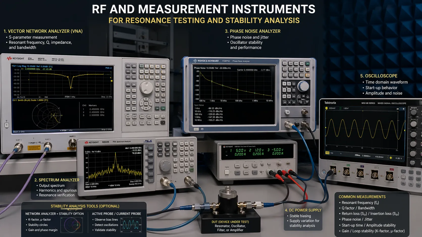
Real-world applications of LC circuits depend on accurate testing, component quality, and controlled operating conditions.
Stability Analysis of LC Resonant Circuits
Component Tolerance and Manufacturing Variation
One of the first threats to stability is component tolerance. Real inductors and capacitors do not come with exact values. Manufacturing variation means that the actual L and C values may differ from the nominal specification, and those differences directly change the resonant frequency.
In broad-response circuits, this shift may be acceptable. In narrowband or frequency-critical systems, however, even a small percentage error can be important. This is why stable resonant designs often use tighter-tolerance parts or provide a trimming method during calibration.
Temperature Drift and Environmental Effects
Temperature changes can alter both inductance and capacitance. Some magnetic materials vary with temperature, and some capacitor dielectrics are more temperature-sensitive than others. As the environment changes, the resonant frequency can drift away from its intended value, especially in precision oscillators and RF circuits.
Environmental stability is not limited to temperature alone. Humidity, vibration, mechanical stress, and enclosure conditions can also affect real performance. In practical engineering, stable resonance depends not only on the schematic but also on the operating environment and packaging strategy.
Loading Effects and Coupling
An LC resonant circuit rarely operates in isolation. It is usually connected to a source, a following amplifier, a measurement instrument, or another resonant stage. These external connections load the circuit and change the effective Q, bandwidth, and sometimes even the apparent resonant frequency.
Loading is especially important during measurement. A probe, cable, or instrument input can unintentionally alter the circuit under test, making the measured resonance different from the free-running internal behavior. Good engineering practice therefore includes measurement-awareness as part of stability analysis.
Parasitic Elements and Layout Sensitivity
Parasitic resistance, parasitic capacitance, and unintended inductive coupling are among the most common reasons that practical LC circuits behave differently from first-pass calculations. At low and medium frequencies, these effects may be modest. At higher frequencies, they can become a defining part of circuit behavior.
Layout discipline is therefore central to stability. Short return paths, sensible grounding, compact placement, controlled trace geometry, and thoughtful shielding all help preserve the intended resonant response. In many RF designs, physical arrangement is almost as important as schematic correctness.
Design Practices for Better Stability
Stable LC resonant circuits are built through disciplined design rather than calculation alone. High-Q inductors, low-loss capacitors, tight-tolerance components, compact layout, and appropriate shielding all contribute directly to better frequency stability and more predictable performance.
It is also wise to reduce unnecessary loading, evaluate temperature behavior early, and verify resonance using both simulation and bench measurement. In demanding designs, component derating, controlled materials, and tuning provisions can make the difference between a theoretically correct circuit and a reliable final product.
The most reliable LC resonant circuits are not simply tuned to the right frequency; they are engineered to stay there under real operating conditions.
Conclusion
LC resonant circuits remain essential because they provide a precise and efficient way to shape frequency behavior in electronic systems. Their core principle is based on energy exchange between an inductor and a capacitor, but successful design depends on much more than the resonance formula alone. Series and parallel topology, Q factor, loss, bandwidth, tolerance, thermal drift, loading, and parasitics all influence final performance.
Whether the goal is RF tuning, oscillation, filtering, or impedance matching, engineers must balance theory with measurement and stability analysis. A strong LC resonant design is not only mathematically correct, but also robust in hardware, consistent in operation, and suitable for the demands of its real application.
FAQ
What is the main purpose of an LC resonant circuit?
The main purpose is to create a strong frequency-selective response. LC resonant circuits are used to pass, reject, generate, or shape signals around a chosen frequency in filters, oscillators, tuners, and matching networks.
What is the difference between series and parallel resonance?
In a series resonant circuit, impedance becomes minimal at resonance and current reaches a maximum. In a parallel resonant circuit, input impedance becomes high at resonance, which makes the circuit useful in tank circuits, tuned loads, and selective frequency networks.
Why is Q factor important in LC circuit design?
Q factor shows how effectively the resonant circuit stores energy compared with how much it loses. A higher Q means sharper selectivity and narrower bandwidth, while a lower Q means broader response and heavier damping.
What causes resonance to become unstable?
Common causes include component tolerance, temperature drift, parasitic capacitance or inductance, resistive loss, poor PCB layout, and loading from connected stages or measurement equipment.
Are LC resonant circuits still important in modern electronics?
Yes. They remain widely used in RF electronics, communication systems, oscillators, analog filters, matching networks, and many types of sensing and signal-processing hardware.
We use cookie to improve your online experience. By continuing to browse this website, you agree to our use of cookie.
Cookies
This Cookie Policy explains how we use cookies and similar technologies when you access or use our website and related services. Please read this Policy together with our Terms and Conditions and Privacy Policy so that you understand how we collect, use, and protect information.
By continuing to access or use our Services, you acknowledge that cookies and similar technologies may be used as described in this Policy, subject to applicable law and your available choices.
Updates to This Cookie Policy
We may revise this Cookie Policy from time to time to reflect changes in legal requirements, technology, or our business practices. When we make updates, the revised version will be posted on this page and will become effective from the date of publication unless otherwise required by law.
Where required, we will provide additional notice or request your consent before applying material changes that affect your rights or choices.
What Are Cookies?
Cookies are small text files placed on your device when you visit a website or interact with certain online content. They help websites recognize your browser or device, remember your preferences, support essential functionality, and improve the overall user experience.
In this Cookie Policy, the term “cookies” also includes similar technologies such as pixels, tags, web beacons, and other tracking tools that perform comparable functions.
Why We Use Cookies
We use cookies to help our website function properly, remember user preferences, enhance website performance, understand how visitors interact with our pages, and support security, analytics, and marketing activities where permitted by law.
We use cookies to keep our website functional, secure, efficient, and more relevant to your browsing experience.
Categories of Cookies We Use
Strictly Necessary Cookies
These cookies are essential for the operation of the website and cannot be disabled in our systems where they are required to provide the service you request. They are typically set in response to actions such as setting privacy preferences, signing in, or submitting forms.
Without these cookies, certain parts of the website may not function correctly.
Functional Cookies
Functional cookies enable enhanced features and personalization, such as remembering your preferences, language settings, or previously selected options. These cookies may be set by us or by third-party providers whose services are integrated into our website.
If you disable these cookies, some services or features may not work as intended.
Performance and Analytics Cookies
These cookies help us understand how visitors use our website by collecting information such as traffic sources, page visits, navigation behavior, and general interaction patterns. In many cases, this information is aggregated and does not directly identify individual users.
We use this information to improve website performance, usability, and content relevance.
Targeting and Advertising Cookies
These cookies may be placed by our advertising or marketing partners to help deliver more relevant ads and measure the effectiveness of campaigns. They may use information about your browsing activity across different websites and services to build a profile of your interests.
These cookies generally do not store directly identifying personal information, but they may identify your browser or device.
First-Party and Third-Party Cookies
Some cookies are set directly by our website and are referred to as first-party cookies. Other cookies are set by third-party services, such as analytics providers, embedded content providers, or advertising partners, and are referred to as third-party cookies.
Third-party providers may use their own cookies in accordance with their own privacy and cookie policies.
Information Collected Through Cookies
Depending on the type of cookie used, the information collected may include browser type, device type, IP address, referring website, pages viewed, time spent on pages, clickstream behavior, and general usage patterns.
This information helps us maintain the website, improve performance, enhance security, and provide a better user experience.
Your Cookie Choices
You can control or disable cookies through your browser settings and, where available, through our cookie consent or preference management tools. Depending on your location, you may also have the right to accept or reject certain categories of cookies, especially those used for analytics, personalization, or advertising purposes.
Please note that blocking or deleting certain cookies may affect the availability, functionality, or performance of some parts of the website.
Restricting cookies may limit certain features and reduce the quality of your experience on the website.
Cookies in Mobile Applications
Where our mobile applications use cookie-like technologies, they are generally limited to those required for core functionality, security, and service delivery. Disabling these essential technologies may affect the normal operation of the application.
We do not use essential mobile application cookies to store unnecessary personal information.
How to Manage Cookies
Most web browsers allow you to manage cookies through browser settings. You can usually choose to block, delete, or receive alerts before cookies are stored. Because browser controls vary, please refer to your browser provider’s support documentation for details on how to manage cookie settings.
Contact Us
If you have any questions about this Cookie Policy or our use of cookies and similar technologies, please contact us at support@becke.cc .